
The miter cut on a radial saw does not forgive approximations. A half-degree deviation on a four-piece frame results in a gap of several millimeters when assembled. We assume here that you already master the basic setup of your machine and are looking to gain precision and repeatability in your joints.
Dust Extraction and Regulatory Constraints on Hardwood Dust
One point that most cutting guides overlook: the quality of dust extraction directly affects the precision of the cut. A poorly connected extraction hood allows sawdust to accumulate between the workpiece and the stop, shifting the actual angle by a few tenths of a degree, enough to compromise a tight joint.
The European Union has set a binding limit value of 2 mg/m³ for hardwood dust (inhalable fraction) in the workplace, effective since January 17, 2023. In Germany, the revised TRGS 553 standard as of February 2025 requires a class M dust extractor with an alert device as a minimum for radial and miter saws.
In practice, we recommend working with the extraction hood closed, using a class M vacuum connected at all times. Check the airflow before each series of cuts. Beyond compliance, a clean cutting area allows for visual control of the angle without having to blow away the sawdust after each pass.
To understand how to successfully make a miter cut with a radial saw, you need to incorporate this extraction constraint from the setup of your workstation.
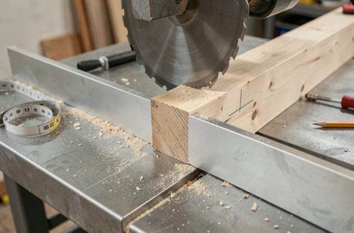
Angle Calibration: Method Using Test Piece Rather Than Protractor
The protractor integrated into the table of the radial saw serves as a starting point, not an absolute reference. On most machines, the engraved graduation has mechanical play. We regularly observe discrepancies that are enough to create a visible gap at the joint.
Verification Protocol in Four Cuts
The most reliable method for validating an angle involves cutting four identical offcuts, assembling them into a closed frame, and measuring the residual gap at the last joint. If the frame does not close perfectly, the total error is divided by eight (four cuts, two faces per joint) to give the correction to apply to the plate.
- Take four offcuts of the same section, with a minimum length of 200 mm, from the same wood as your final piece.
- Cut each end at 45 degrees, totaling eight cuts, without changing the setting between passes.
- Assemble the frame dry with masking tape and measure the residual opening at the last angle.
- Correct the plate by a quarter of the measured gap, then repeat the test until you achieve an invisible joint.
This approach eliminates the inaccuracy of the protractor, that of the eye, and that of the blade itself (deflection, lateral wear). The test piece remains the only reliable standard for a quality miter cut.
Choice and Condition of the Blade for Clean Miter Cuts
A blade with alternating teeth and a high tooth count reduces chipping, but that is only part of the equation. The determining factor is the condition of the carbide, not the number of teeth. A slightly dull 60-tooth blade produces a result inferior to a perfectly sharpened 48-tooth blade.
For hardwoods and veneered MDF, we recommend a blade with a negative or zero rake angle. The negative angle prevents the tooth from “biting” into the wood and pulls the piece toward the stop instead of pushing it away, stabilizing the cut.
Reducing Chipping at the Blade Exit
Chipping always occurs on the exit side of the tooth. On a radial saw, the blade descends toward the piece, so the chips appear on the underside. For cuts visible on both sides:
- Apply a wide masking tape along the cut line, on the underside of the piece. The tape holds the fibers during the passage of the tooth.
- Adjust the descent speed so that the blade advances slowly in the last third of the thickness, where the wood is no longer supported.
- Regularly replace the saw line of the sacrificial plate (zero play insert). A worn insert leaves a gap under the piece that promotes tearing.
A new zero play insert eliminates most chipping without changing blades or slowing down the pace.
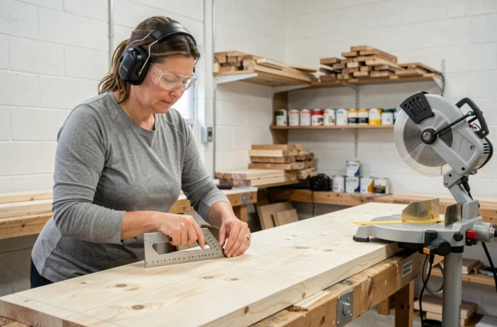
Stop and Holding the Piece: The Most Underestimated Source of Error
On a 45-degree miter, the lateral component of the cutting force pushes the piece along the stop. If the piece slips, even by a few tenths of a millimeter during the descent of the blade, the joint will be misaligned.
The simplest solution is a cam clamp fixed to the stop, which holds the piece without deformation. Spring clamps are suitable for softwood, but lack rigidity on oak or beech. The cam clamp provides constant holding regardless of the wood species.
Another often overlooked point: the flatness of the stop itself. A slightly bowed stop creates a two-point support, and the piece pivots under the pressure of the clamp. We check the stop with a precision ruler before each series of critical miter cuts. If a dip appears, a rectified aluminum shim glued to the stop permanently corrects the issue.
Coping: The Alternative to Miter Cuts for Interior Angles of Molding
On profiled moldings, the miter cut at an interior angle poses a structural problem: wood shrinkage opens the joint over the seasons, regardless of the care taken in the cut. The coping technique involves cutting the profile of the molding on one of the two pieces so that it fits the relief of the other.
The principle is simple: cut the first piece at 90 degrees, fitted into the corner. The second piece first receives a 45-degree cut on the radial saw, then the visible profile is cut with a jigsaw following the line of the miter. The coped piece fits onto the first without relying on the exact geometry of the wall.
This method applies to baseboards, chair rails, and crown moldings. It takes a bit more time per joint, but the result remains stable over time, even on walls that do not form a perfect 90-degree angle.
The perfect miter cut relies less on the machine than on controlling each peripheral variable: extraction, calibration using a test piece, condition of the carbide, holding the piece. Mastering these four parameters transforms a standard radial saw into a precision tool.